I. Composition and Classification of Optical Fibers
Optical fibers can be classified into quartz optical fibers and plastic optical fibers based on the material used in their manufacturing. Quartz optical fibers are the commonly used type, and they are further divided into single-mode and multi-mode fibers based on their transmission modes. Plastic optical fibers are entirely made of plastic, typically used for short-distance multi-mode applications, and are still in the early stages of development with no large-scale application.
Structure of Quartz Optical Fibers: Quartz optical fibers are composed of the core, cladding, and coating layers. Light transmission occurs in the core of the optical fiber. Due to the difference in refractive indices between the core and cladding, total internal reflection occurs at the interface, allowing the light to stay within the core. The plastic coating layer serves to protect the fragile quartz fiber and enhance the strength of the optical fiber. Without this plastic protection, the fiber would be impractical for use, even though it has some tensile strength.
Classification of Quartz Optical Fibers:
Single-mode Optical Fibers:
G.652A (B1.1, abbreviated B1)
G.652B (B1.1, abbreviated B1)
G.652C (B1.3)
G.652D (B1.3)
G.655A Optical Fiber (B4) (Used in long-distance trunk lines)
G.655B Optical Fiber (B4) (Used in long-distance trunk lines)
G.657A2 (Indoor butterfly cables)
Multi-mode Optical Fibers:
50/125 (A1a, abbreviated A1)
62.5/125 (A1b)
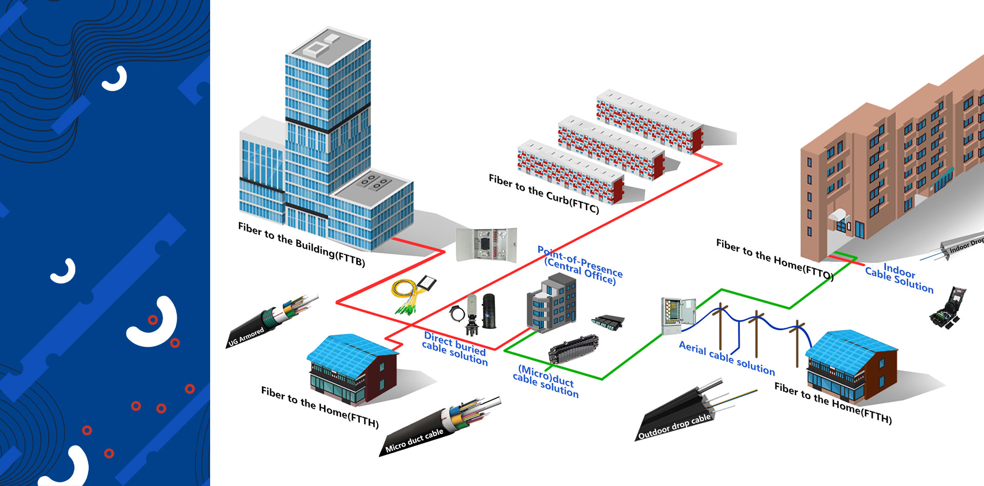
II. Structure of Optical Cables
Outdoor Optical Cables: There are three main types: center-tube optical cables, stranded optical cables, and skeleton optical cables. These can further be divided into six types based on the use of fiber bundles or optical fiber tapes. The structural features of each type are as follows:
Center-Tube Optical Cable (Standard: YD/T769-2003): The core of the cable consists of loose tubes, with reinforcement elements located around these tubes. This type is commonly used for cables with fewer fibers, typically less than 12 fibers.
Stranded Optical Cable (Standard: YD/T901-2009): Reinforcement elements are located at the center, with 5 to 12 loose tubes twisted together around the central strength member, usually using SZ stranding. This structure allows for higher fiber counts, with the company currently offering cables with up to 216 fibers or more.
Skeleton Optical Cable: The reinforcement elements are located at the center, with plastic skeleton grooves to hold the optical fiber or fiber tape. This structure offers excellent resistance to compression and is rarely seen in the domestic market.
Figure-8 Self-supporting Structure: This structure can be integrated into both center-tube and stranded optical cables but is highlighted separately due to its distinct design. This cable is designed for self-supporting overhead installations.
Flame-retardant Optical Cable for Coal Mines (Standard: Q/M01-2004, Enterprise Standard): This cable has enhanced flame-retardant properties for use in mines. The outer sheath is usually blue for easy identification in mining environments.
Indoor Optical Cables: Indoor optical cables are classified by the number of fibers, including single-fiber, dual-fiber, and multi-fiber cables. They consist of tight-buffered fibers, spunbond, and PVC outer sheaths. Indoor cables are further divided into single-mode and multi-mode types. Single-mode indoor cables typically have yellow outer sheaths, while multi-mode cables have orange outer sheaths. Some indoor cables may have gray outer sheaths.
III. Naming Method of Optical Cable Models (YD/T908-2000)
Optical Cable Model Composition:
I: Represents the type of optical cable.
GY: Communication outdoor optical cable
GJ: Indoor optical cable
MG: Coal mine optical cable
II: Type of reinforcement.
(No symbol): Metal reinforcement
F: Non-metal reinforcement
III: Structural features.
D: Optical fiber tape structure
(No symbol): Loose tube stranded structure
X: Center-tube structure
G: Skeleton structure
T: Filling structure
Z: Flame-retardant structure
C8: Figure-8 self-supporting structure
IV: Sheath material.
Y: Polyethylene sheath
W: Steel-wire polyethylene bonded sheath
S: Steel-polyethylene bonded sheath
A: Aluminum-polyethylene bonded sheath
V: PVC sheath
V: Outer sheath.
53: Wrinkled steel tape longitudinally armored polyethylene sheath
23: Steel tape armored polyethylene sheath
33: Fine steel wire armored polyethylene sheath
43: Coarse steel wire armored polyethylene sheath
333: Double fine steel wire armored polyethylene sheath
Optical Cable Specifications:
The specification is expressed by the number of fibers and their type. For example, a cable with 4 G.652 single-mode fibers would be denoted as 4B1.1 or 4B1. If the cable contains different types of fibers, they are separated by a ‘+’ sign.
Common Model Descriptions:
GYXTW: Metal reinforcement, center-tube filling, steel-wire polyethylene bonded sheath, suitable for outdoor communication cables in pipelines and overhead installations.
GYXTW53: Metal reinforcement, center-tube filling, steel-wire polyethylene bonded sheath with longitudinal steel tape armoring, suitable for direct-burial installations.
GYTA: Metal reinforcement, loose tube stranded filling, aluminum-polyethylene bonded sheath, suitable for outdoor communication cables in pipelines and overhead installations.
GYTS: Metal reinforcement, loose tube stranded filling, steel-polyethylene bonded sheath, suitable for outdoor communication cables in pipelines and overhead installations.
IV. Usage Scenarios and Key Performance Indicators of Optical Cables
Usage: Single-sheath cables are typically used for overhead and pipeline installations, while double-sheath cables are used for direct-burial installations. Indoor cables are used in buildings and indoor environments.
Key Performance Indicators:
Attenuation: An important indicator of fiber performance, used to monitor production and process issues. For example, the attenuation requirements for single-mode and multi-mode fibers include:
B1.1 (Single-mode): 1310nm ≤ 0.36db/km, 1550nm ≤ 0.22db/km
A1a (Multi-mode 50/125): 850nm ≤ 2.5db/km, 1300nm ≤ 0.7db/km
V. Optical Cable Manufacturing Process
Fiber Coloring Process: The main goal is to apply clear, smooth, and stable colors to fibers for easy identification during cable production and use. The coloring process uses optical fibers and coloring inks, with 12 standard colors.
Second Coating Process: The second coating process involves applying a suitable polymer material to the optical fiber using extrusion. This process ensures long-term protection of the fiber with proper water resistance and compatibility with the outer coating material.
Stranding Process: The stranding process, or cabling process, is critical for increasing flexibility and improving the cable’s tensile strength and temperature characteristics. The main control indicators include stranding pitch, yarn binding tension, and tension during the stranding process.
Sheath Process: Depending on the installation environment, the optical cable receives various protective sheaths to meet mechanical protection requirements. The sheath must withstand external mechanical forces, environmental temperature variations, and chemical corrosion during its lifespan.
Post time: Feb-28-2025